Panyu District, Guangzhou · Manufacturing since 2013
Tube OD Ø4–150 mm hi@newsiyuantube.com
NewSiyuan TubeTube Bending · Panyu, Guangzhou WhatsApp

Home / Tube Bending / Tolerances

Tube Bending Tolerances: What ±1° and ±1 mm Actually Mean

Typical custom tube bending tolerances at our shop are ±1 degree on bend angle, ±1 mm on centreline radius and tangent length, and ±0.5 mm on cut length. We are NewSiyuan Tube, a tube bending factory in Guangzhou, and we hold these on tube from 4 to 150 mm OD. Wall thinning stays within 15% and ovality within 8%. This page explains what each limit means physically and what to write on your drawing.

The six figures, in plain languageEach one means something different to the person setting the machine.

A tolerance list is only useful if you know what is being measured and where. Six numbers appear on almost every bent tube enquiry, and two of them are routinely misread — the centreline radius and the bend angle.

Bend angle ±1°One degree either side of the angle on your drawing, measured against the bending fixture rather than by eye. Its effect in millimetres grows with the length of the straight section after the bend — see the table below.
Centreline radius ±1 mmThe radius measured at the centreline of the tube, not the outside of the bend. The die is specified on the centreline, so this is the figure the tooling can actually be set to.
Tangent length ±1 mmThe straight run between the end of a bend and the next feature — a hole, a notch, the start of the next bend. It controls whether the part locates in your fixture.
Cut length ±0.5 mmOverall length after cutting and before any end forming. If the ends get flared, threaded or notched afterwards, those operations carry their own allowance.
Wall thinning ≤15%Measured on the outside of the bend and expressed against the nominal wall. Bending stretches the outer arc and compresses the inner one, so the thin point is always on the outside.
Ovality ≤8%The difference between the largest and smallest diameter across the bend, as a percentage of nominal outside diameter. A Ø50 tube can go oval by up to 4 mm and still sit inside this limit.

These are inspection criteria for standard bends on the materials and radii we quote, not a guarantee for every geometry. Tight radii, thin walls and hard alloys are assessed part by part. The same criteria are used on the inspection page and on the tube bending page; this page is where each one is unpacked.

What one degree and fifteen percent cost youTwo numbers decide whether an assembly closes.

A bend angle quoted in degrees feels small. On a long part it is not. The far end of a straight run swings sideways in proportion to its length, so the same one degree that is invisible on a 100 mm bracket becomes a visible gap on a 1 m frame.

Straight run after the bend100 mm → about 1.7 mm of end displacement from one degree of angular error
300 mm → about 5 mm
600 mm → about 10.5 mm
1000 mm → about 17 mm

Wall thinning is the number that decides whether a part is safe to use rather than whether it fits. A 2 mm wall with 15% thinning is 1.7 mm at the outside of the bend. On a handrail post that is irrelevant. On a pressurised or load-bearing part it is the difference between a design that holds and one that fails slowly. Ovality matters in a different place: it decides whether a sleeve, a clamp or a tube insert still fits over the bend, and it is the reason a bent tube sometimes will not take a straight connector.
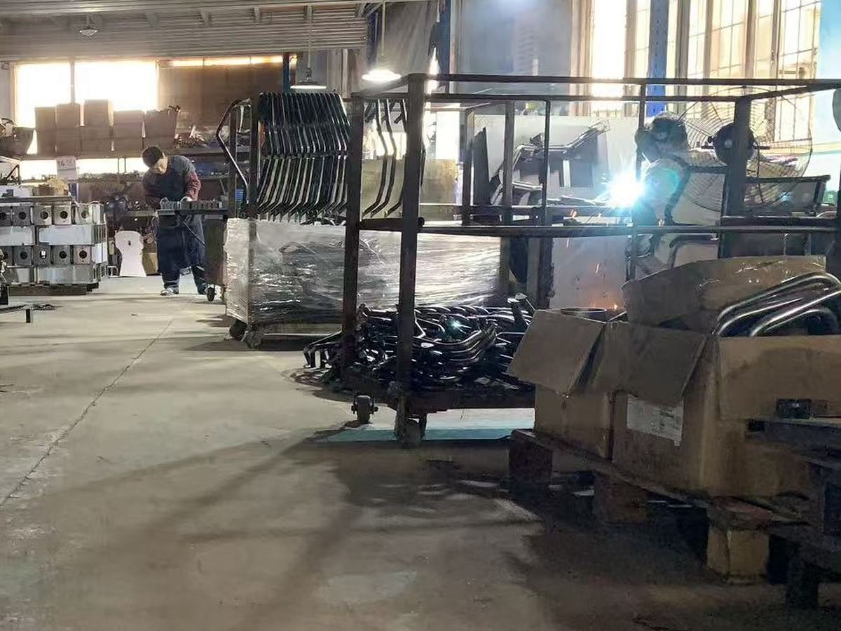
Racks of bent tube frames waiting for the next operation
Bent frames racked by part number. Measuring the first and the last piece of a run is how a radius is proven to hold across a batch, not a single sample.

How big a tube we can bendAnd the one number that gets misquoted most often.

Bending runs from Ø4 to Ø150 mm outside diameter, in round, square and oval section, with wall from 0.8 to 5 mm. Carbon steel, 304 and 316L stainless, aluminium 6061, 6063 and 7075, copper and brass all run on the same floor. Above Ø90 mm there is one machine that can take the size, so those jobs are scheduled around it and lead time is quoted per part — not promised as a standard figure.

Bending rangeØ4–150 mm OD · wall 0.8–5 mm · round, square, oval
Above Ø90 mmOne machine in this class — schedule is quoted per part, and the date is given after the drawing is checked
Laser tube cuttingØ220 mm × 6 m on two machines — cutting only. Tube that is laser cut is bent on the bending machines above, not on the laser.
Aluminium6061, 6063 and 7075 bend; some tempers need annealing first, which is decided at the feasibility check

A Ø220 mm tube can be cut here but not bent here. If a drawing needs both, the cutting is ours and the bending above Ø150 mm is not — say so early rather than at the sample stage. This distinction is also set out on the tube bending page.

Tooling and the timeline it setsThe die on the rack is the reason one quote is three days and another is a month.

Sample lead time is decided almost entirely by whether a die of the right centreline radius already exists. Three days assumes standard tube, a clear drawing and a die that is on the rack. Anything else moves the date, and the honest version of the date is given after the drawing has been read.

Standard tube, die on the rack3 days to a sample, MOQ 1 piece
Material not in stock7–10 days to bring the tube in before bending starts
New die requiredAbout 2 weeks to make the tooling
Then the first article3–5 days after tooling is ready, measured and reported before the batch is released
Production run25–40 days after sample approval, splittable into batches if you need part of the order earlier
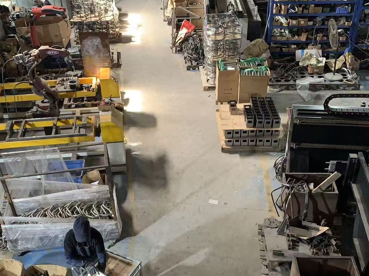
Overhead view of the tube bending shop floor with machines arranged by capacity
Machines arranged by the diameter class they cover. Which machine takes the job is decided by the tube size, and that decision sets the sample date.

What to put on the drawingSeven items that prevent most tolerance arguments.

Most quoting delays come from a drawing that describes the part in a way the tooling cannot be set from. These are the items that make a drawing quotable on the first pass, whether you send it to us or to anyone else.

1. Centreline radius per bendNot an outside radius, and not "R50 approx". Where a bend is a free-form sweep, say so and give the start and end tangents.
2. Bend angle per bendIncluded angle or deflection — either is fine, but mark which one. "90°" on a drawing is ambiguous when the part is bent twice in the same plane.
3. Tangent lengthsThe straight between bends. This is the dimension that decides whether the part assembles; overall length alone does not.
4. Cut length, or the datum you measure fromIf overall length is measured after end forming, say which operation comes last.
5. Material and wallGrade and nominal wall, in writing. "Stainless" is not enough to choose a die or predict springback.
6. Which dimensions are criticalMark the two or three that must hold. It changes how the part is measured and sometimes which machine it runs on.
7. Surface finish and its sequenceIf the part is coated or polished, say whether it is inspected before or after. Measuring after coating measures the coating too.

Send a PDF or a STEP file to hi@newsiyuantube.com or on WhatsApp. The first reply says whether the radius, wall and material are workable, and which dimensions we would flag before quoting.

Where these tolerances stop applyingRead this before you assume the table covers your part.

  1. Not a guarantee for every geometry. The figures describe standard bends on quoted materials. Tight radius, thin wall, hard temper and multi-bend parts in one plane are all assessed individually, and the achievable tolerance is stated at quotation.
  2. No bending above Ø150 mm. Laser cutting reaches Ø220 mm, bending does not. A drawing that needs a bend bigger than Ø150 mm is not a job we can take, whatever the cutting capability suggests.
  3. No EN 1090 structural certification. We machine and bend to drawing and report dimensions. Structural steelwork to that standard is outside our scope.
  4. No safety-critical parts. Forks, brake components, steering parts and similar are not made here — there is no fatigue testing behind them, and a tolerance table is not a substitute for type approval.
  5. No post-hoc paperwork. If a dimensional report or a material certificate is needed, it has to be agreed before the order. Material certificates to EN 10204 3.1 come from the material mill and depend on the raw-material batch.
  6. Tighter than the table is a conversation, not a catalogue line. If your assembly needs ±0.3 mm, send the drawing and the reason. If it cannot be held, you will hear that before the order, not after the inspection.

General information only — not engineering advice. Suitability for a specific application, load case or service environment must be confirmed by the buyer's engineer.

Tolerance questions we get asked

What does ±1° on a bend angle mean in millimetres?
It depends on how long the leg after the bend is. One degree of angular error moves the far end of a straight run by roughly 1.7 mm for every 100 mm of that run. A 300 mm leg can end up 5 mm away from where the drawing puts it, and a 1000 mm leg about 17 mm. That is why a tolerance quoted in degrees has to be read together with the leg length.
Is wall thinning measured on the inside or the outside of the bend?
The outside. Bending stretches the outer wall and compresses the inner wall, so the thinnest section sits on the outside of the arc. Thinning within 15% means a 2 mm wall is still at least 1.7 mm at that point.
Can you hold a tighter tolerance than ±1 mm if the part needs it?
Often yes, on a specific part with a specific wall and radius, but it is quoted per drawing and agreed before the order. It is not a catalogue figure we can promise across every geometry. Where it cannot be held we say so at quotation.
Why does the drawing need a centreline radius instead of an outside radius?
The machine bends around a die whose radius is measured on the centreline of the tube, and the radius you see on the outside of the bend varies with wall thickness and springback. A centreline radius and a bend angle describe the part the tooling has to produce; an outside radius has to be converted before the die can be chosen.

Send the drawing and the two critical dimensions.

The first reply says whether the radius and wall can hold your tolerance, and where the risk is on that specific part.

WhatsApp